332 Results
View results:
Sort by:
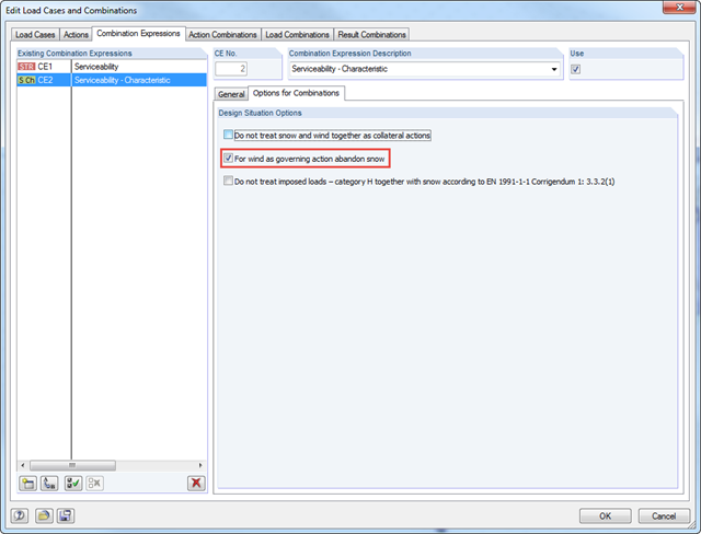
According to DIN EN 1990/NA:2010‑12 - NDP to A.1.2.1(1) Comment 2, it is possible to neglect the combination of snow as a collateral action in cases of wind/snow combination with wind as the leading action in wind zones III and IV.

A new capability within RFEM 6 when designing concrete columns is being able to generate the moment interaction diagram according to the ACI 318-19 [1]. When designing reinforced concrete members, the moment interaction diagram is an essential tool. The moment interaction diagram represents the relationship between the bending moment and axial force at any given point along a reinforced member. Valuable information is shown visually like strength and how the concrete behaves under different loading conditions.

In addition to the basic combination rules of EN 1990, there are other combination conditions for actions on road bridges specified in EN 1991‑2 that must be taken into account. RFEM and RSTAB provide automatic combinatorics that can be activated in the General Data when selecting the standard EN 1990 + EN 1991‑2. The partial safety factors and combination coefficients depending on the action category are preset when selecting the respective National Annex.

Silos are used as large containers for storage of bulk materials such as agricultural products or source materials as well as intermediates of industrial production. The structural engineering of such structures requires a precise knowledge of the stresses due to particulate solids in the building structure. The standard EN 1991‑4 "Actions on Silos and Tanks" [1] provides the general principles and requirements for determining these actions.
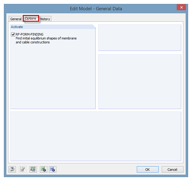
The RF‑FORM‑FINDING add‑on module can be activated in the "Edit Model - General Data" window, "Options" tab. By activating the module, a new RF‑FORM‑FINDING load case is created and an additional menu appears in the main program, allowing for the definition of prestress conditions for membrane and cable elements.
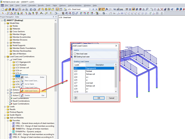
If you want to import a block with previously saved loads into an existing model, the load cases are not integrated into the existing load cases, but are added to the existing ones.
You can select an object in RFEM or RSTAB by simply clicking it. However, only the last object clicked will stay selected. In order to select several objects at a time, press the Control key while clicking. Since this procedure is not always possible, you can use the "Add to Selection" function in the toolbar or in the "Edit" → "Select" menu.
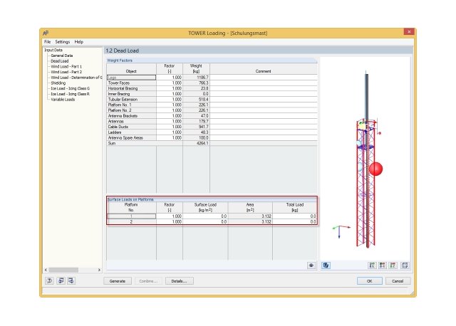
In the RFEM 5.04.0024 and RSTAB 8.04.0024 versions, there is a new feature in RF‑/TOWER Loading that allows you to define additional surface loads in a load case for dead loads; for example, from grids on platforms.
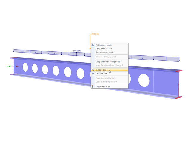
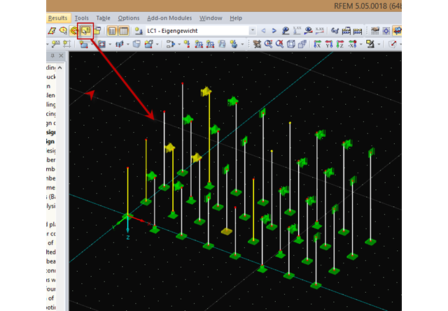
The display size of the load vectors can be adjusted quickly in the load shortcut menu: Right-click the load icon and select "Increase Display Size" or "Reduce Display Size" from the menu.
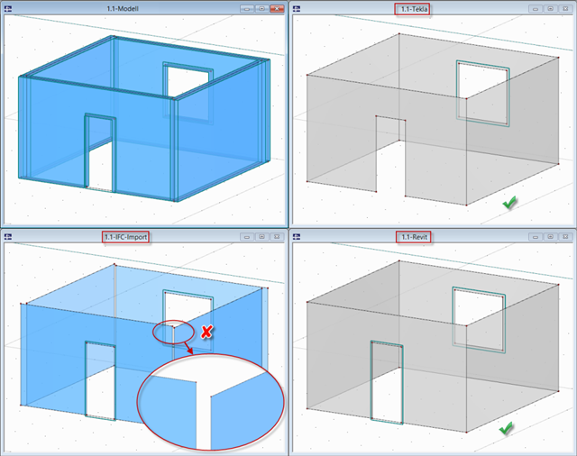
In RFEM and RSTAB, several interfaces are available. The DSTV interface (*.stp) is the most convenient for importing beam structures, since supports, hinges, loads, and load combinations are also transferred, in addition to the general topology.
.png?mw=640&hash=8fd04a597cecae2e434980ce79fc626815a5d98a)
The Aluminum Design Manual (ADM) 2020 was released in February 2020. The ADM 2020 gives guidance for both the allowable strength design (ASD) and load and resistance factor design (LRFD) for aluminum members to ensure reliability and safety for all aluminum structures. This latest standard was integrated in the RFEM/RSTAB add-on module RF-/ALUMINUM ADM. The text below will highlight the applicable updates relevant to the Dlubal programs.

When designing bending-resistant connections from I-beams, the connection is dissolved into the individual parts. For these basic components of a joint, there are separate formula calculators for load-bearing capacity and stiffness. In RFEM and RSTAB, frame joints can be designed using the RF-/FRAME-JOINT Pro add-on module.
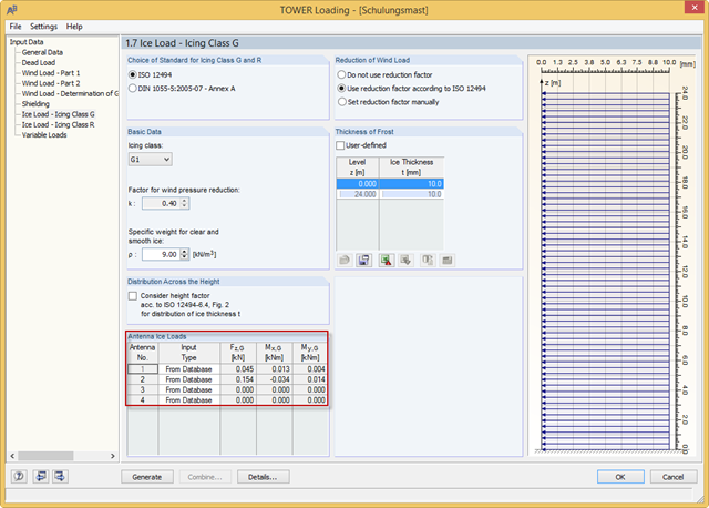
With the RFEM 5.04.0024 and RSTAB 8.04.0024 versions, you can define the antenna ice loads in RF‑/TOWER Loading. The program provides the values from the manufacturer databases. In addition, you can define the ice loads manually or use the calculation based on simplified geometry.
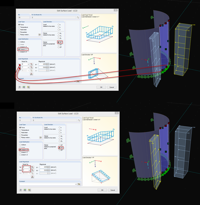
If you want to apply, for example, wind loads to a circular cylinder as defined in EN 1991‑4, Clause 7.9, proceed as follows.
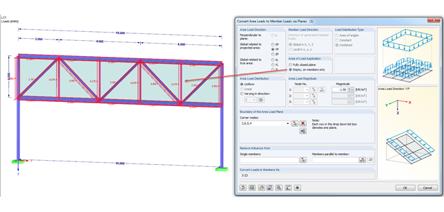
There are two selection options for the area of load application when generating loads: "From Area Loads via Plane" and "From Area Loads via Cells".

The ASCE 7-22 Standard [1], Sect. 12.9.1.6 specifies when P-delta effects should be considered when running a modal response spectrum analysis for seismic design. In the NBC 2020 [2], Sent. 4.1.8.3.8.c gives only a short requirement that sway effects due to the interaction of gravity loads with the deformed structure should be considered. Therefore, there may be situations where second-order effects, also known as P-delta, must be considered when carrying out a seismic analysis.
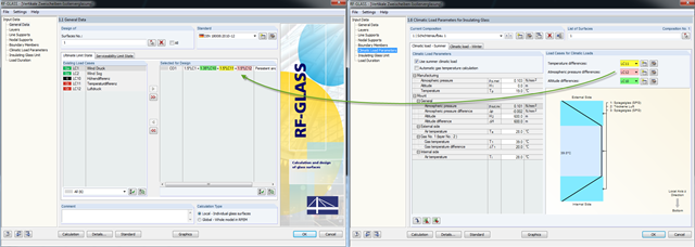
A new feature allows you to assign climatic loads to load cases when designing panes of insulating glass. Climatic loads are included in three categories here: temperature difference, atmospheric pressure difference, and altitude difference.

For the stability verification of members using the equivalent member method, it is necessary to define effective or lateral-torsional buckling lengths in order to determine a critical load for stability failure. In this article an RFEM 6-specific function is presented, by which you can assign an eccentricity to the nodal supports and thus influence the determination of the critical bending moment considered in the stability analysis.

As in RFEM, load combinations can be generated automatically in RF‑PIPING. This feature is activated by default and creates the recommended load and result combinations for piping design. It is necessary to assign the relevant action category to load cases in order to generate the correct combinations. To do this, new action categories have been implemented specifically for loads on piping.
Pressure temperature conditions are generated as the sets of the first (second, third, and so on) load case of the "Pressure" category and the first (second, third, and so on) load case of the "Temperature" category. The default setting can be reviewed or adjusted in the "Grouping of Thermal and Internal Pressure Load Cases for Operating Combinations" dialog box. You can access this dialog box by clicking the corresponding button in the "Piping Load Combinations" tab of the "Load Cases and Combinations" dialog box. This dialog box is automatically offered to check your entries in the case of any change of the load case from the "Pressure" or "Temperature" category.
Pressure temperature conditions are generated as the sets of the first (second, third, and so on) load case of the "Pressure" category and the first (second, third, and so on) load case of the "Temperature" category. The default setting can be reviewed or adjusted in the "Grouping of Thermal and Internal Pressure Load Cases for Operating Combinations" dialog box. You can access this dialog box by clicking the corresponding button in the "Piping Load Combinations" tab of the "Load Cases and Combinations" dialog box. This dialog box is automatically offered to check your entries in the case of any change of the load case from the "Pressure" or "Temperature" category.
.png?mw=640&hash=6e011ea537587ceb48d9e642d642150a151c551e)
The ASCE 7-16 standard requires both balanced and unbalanced snow load case scenarios for a structure's design consideration. While this may be more intuitive for flat or even gable/hip type roofs, the determination of snow loads is increasingly difficult for arch roofs due to complex geometry. However, with guidance from ASCE 7-16 on snow load calculations for curved roofs and RFEM's efficient load application tools, it is possible to consider both balanced and unbalanced snow loads for a reliable and safe structure design.

In January 2015, DIN Committee NA 005‑08‑23 Steel Bridges applied the introduction of a modification in equation 10.5 of DIN EN 1993‑1‑5. This involves the interaction of longitudinal and transverse pressure in a buckling analysis. Now, the interaction equation provides for auxiliary factor V, which is calculated from the reduction factors of the longitudinal and transverse stresses.

The events of recent years remind us of the importance of earthquake engineering in seismic regions. For you as an engineer, the design of structures in earthquake-prone areas is a constant trade-off between economic efficiency – the financial possibilities – and structural safety. If a collapse is inevitable, engineers must estimate how it will affect the structure. This article aims to provide you with an option on how to perform this estimation.
This article describes the design of timber panel walls due to generated horizontal loads.

This article deals with elements concerning which the cross-section is subjected simultaneously to a bending moment, a shear force, and an axial compressive or tensile force. However, in our example we will not include loading due to shear force.

This article deals with the determination of the concrete reinforcement for a beam stressed by tension only according to EN 1992-1-1. The aim is to show the tensile load of a member-type element (without imposed deformations) and to define the concrete reinforcement in accordance with the standard's construction rules and provisions using the RFEM structural analysis software.

In the case of open cross-sections, the torsional load is removed mainly via secondary torsion, since the St. Venant torsional stiffness is low compared to the warping stiffness. Therefore, warping stiffeners in the cross-section are particularly interesting for the lateral-torsional buckling analysis, as they can significantly reduce the rotation. For this, end plates or welded stiffeners and sections are suitable.

Before creating a structural model, every user gives thought to the boundary parameters of the system and how best to represent the model. Special attention should be paid to the orientation of the global coordinate system. In engineering, the global Z‑axis is usually oriented downwards (in the direction of the dead load), while it tends to be upwards in architecture. These differences can often lead to complications during modeling; for example, when you replace global models or DXF layers.
RF‑/FOUNDATION Pro allows you to check the allowable eccentricity of the soil pressure resultants. According to DIN EN p;1997‑1/NA, this design is to be carried out with characteristic or representative loads.
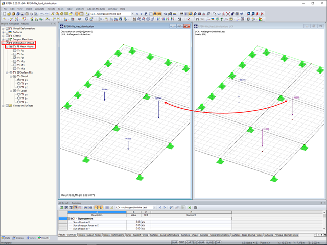
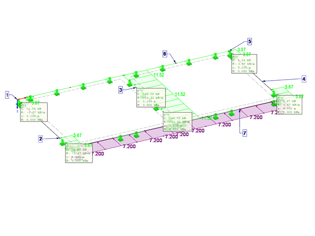
In RFEM, the load distribution is available for the result evaluation.
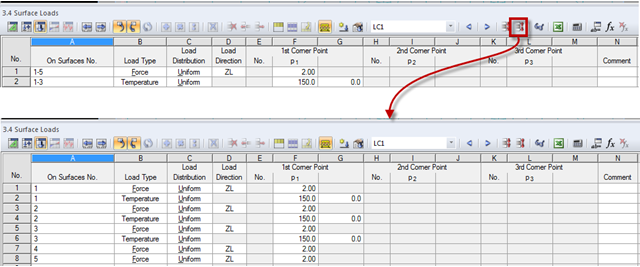
The load tables provide a simple option to control the applied loads. Dividing loads into individual lines is expedient. After dividing loads into the load table, the load data are displayed by a structural element (nodes, members, lines, surfaces, or solids). Thus, the load data analysis of each structural element is facilitated. The load case data can be compressed later.